2026-09-29 2
The nozzle and oil supply line need to cooperate with each other in connection, layout and medium transportation. Design inputs should clarify the interface form, installation space and maintenance conditions.
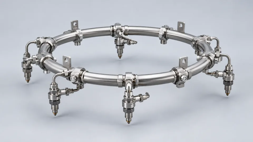
The interface between the nozzle and the pipeline also involves direction, assembly space, and maintenance accessibility. These factors should be considered during the design phase, along with related components, to prevent problems where individual parts may meet requirements, but installation or inspection becomes difficult when combined.
The internal state of the fuel supply channels needs to be continuously managed during manufacturing, storage, and assembly. Proper protection of openings, sequential inspections, and pre-assembly verification can form a complete process. Specific cleaning requirements should come from product documentation, rather than being determined based on visual inspection alone.
During manufacturing and assembly processes, attention should be paid to channel cleanliness, connection status, and identification markings. Test items and acceptance criteria should be determined according to product requirements.
Individual tests can answer different questions compared to combined tests. Individual results help evaluate the overall system, while combined tests involve interfaces and interactions between components. When scheduling tests, it’s important to specify the test boundaries, so that conclusions drawn from one level cannot be generalized to another level without proper justification.
When there are abnormalities in supply or spraying performance, it’s important to document the pipeline connections, testing conditions, and component identities, then gradually investigate the relevant aspects. Changing only specific conditions at a time and keeping records helps to determine the source of the differences, preventing loss of clues due to simultaneous adjustments in multiple areas.
It is assumed that no issues were found during individual component inspections. However, if there are any changes in performance after being incorporated into the supply system, it’s necessary to check the connection directions, supply conditions, and the status of other components. Each investigation should record what has changed, so as to determine whether the results have also changed accordingly. Individual test results are still valuable, but they cannot cover all conditions within a combined system. They must be understood within appropriate boundaries.
Investigations should be guided by evidence and interface relationships. Blindly replacing components might temporarily change the situation, but it may not provide an explanation for the changes, and it could also lead to the loss of important clues from the original state.
When there are changes in system performance, it’s necessary to conduct comprehensive checks involving pipelines, interfaces, and the entire nozzle system. Avoid making conclusions based solely on the behavior of a single component.