2026-09-29 1
Components in the combustor system jointly participate in combustion organization and high-temperature air flow transportation. Understanding system interfaces helps clarify the design and manufacturing concerns of individual parts.
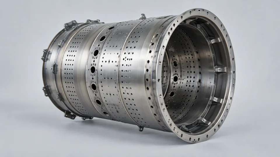
The combustion chamber organizes the combustion process of fuel and air within its structure, and delivers high-temperature airflow to subsequent components. Therefore, understanding the combustion chamber requires consideration of both the supply area and the downstream interfaces. It cannot be seen as just an independent metal cylinder.
The flame tube, connection structures, and transition areas each play different roles within the system. When interpreting component drawings, it is important to consider their position within the system and understand which features are related to connections, and which are related to airflow or thermal conditions. All requirements should still be based on the corresponding design documents.
The geometric requirements for the flame tube, connection structures, and transition areas should be understood in conjunction with the overall design. Local optimizations for individual components must take into account both assembly considerations and system impacts.
Whether changes in local shape or position affect assembly or operation needs to be evaluated within the context of the entire system. Manufacturers should provide information on actual deviations and positions, and designers should assess the impact based on this information, avoiding conclusions based solely on superficial similarities.
From the design review to prototype testing, and then to functional testing, the issues addressed vary at each stage. Records should clearly indicate the objects and versions being verified at each step. Only after further modifications can we determine which conclusions can be reused and which need to be re-verified.
It is assumed that there may be dimensional discrepancies at certain joints in the combustion chamber components. The manufacturing side should provide information regarding the location of these discrepancies, the actual values, and the condition of the components. During the design review, it is necessary to consider the impact on the entire system and its interfaces, rather than simply assessing whether a component can be assembled or not. The review conclusions should clearly define the applicable objects and the scope of actions required, to avoid making decisions based on individual components becoming universal rules for subsequent products.
Images can help understand the structure, but they cannot provide information about operating conditions, material properties, or verification results. Thermal performance must be determined through design analysis and appropriate testing, and cannot be inferred from appearance alone.
During the engineering development process, solutions can be gradually verified through design reviews, prototype testing, and functional testing, rather than making judgments about component performance based solely on appearance.
Further reading:NASA: How combustion chambers work