2026-09-29 6
The manufacturing of spray guide related parts needs to pay attention to the relationship between shapes, channels and assembly interfaces. Process planning should be based on the functional requirements of the complete part.
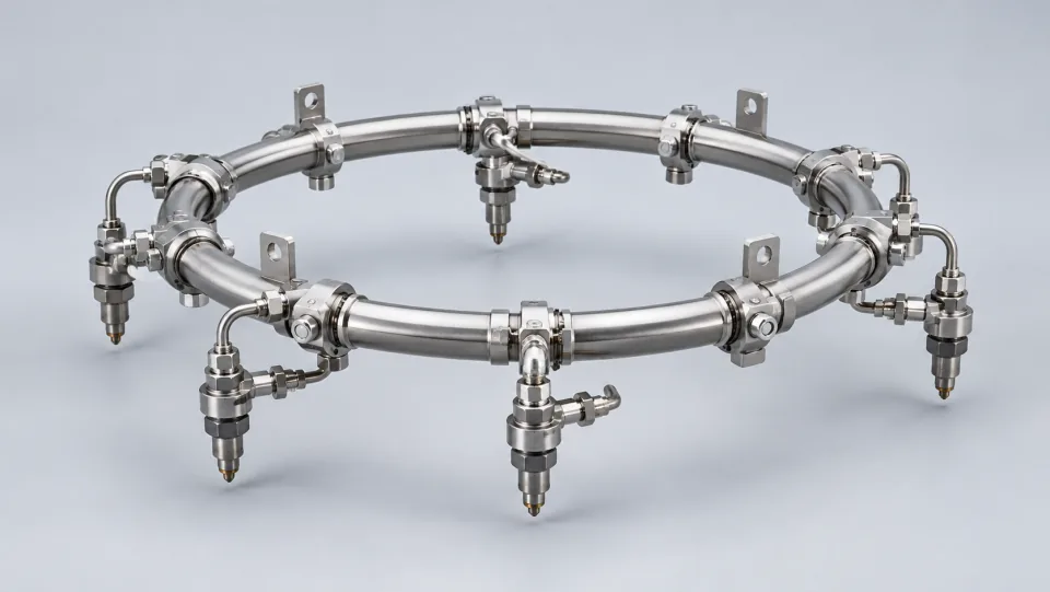
Components related to jet guidance may include various features such as surfaces, holes, and connections. During manufacturing preparation, these requirements can be associated with the corresponding processes, indicating which features need to maintain their relative positions, and which areas are difficult to inspect later.
After processing, it is necessary to confirm the state of holes, edges, and surfaces as required. Protection measures for transitions should be chosen based on the actual structure, to avoid interference from foreign objects or damage that could affect the next step in the process. For hidden areas, the method of inspection and the location of records must be clearly defined; mere cleanliness cannot suffice as a confirmation.
In the arrangement of processes, it is necessary to determine which features are used for positioning, which areas need to be inspected before subsequent connections, and to consider cleaning and protection requirements.
After the local processing of parts is completed, it is important to verify the relationships between the parts and their components. The direction of interfaces, positioning features, and assembly space can be checked during the process review. Any discrepancies found should be reported according to the established procedures, rather than being resolved through unverified on-site adjustments.
When describing issues, using feature numbers, position indications, and actual data makes it easier to support the review process. Keeping track of the process and part states where problems occur helps in determining the cause and the scope of subsequent actions.
It is assumed that certain holes may be difficult to access after the parts are assembled. Therefore, the manufacturing plan should clearly define the inspection and protection requirements before assembly. After the inspection is completed, it is also necessary to consider whether any subsequent operations might alter the internal state of the parts. Records should not only indicate that inspections have been conducted, but also ensure that the current state remains under control. This way, processing, inspection, and assembly can be integrated into a continuous process.
Local results should only support the relevant features. The overall state may also involve positional relationships, channels, interfaces, and other requirements, which need to be evaluated according to a comprehensive inspection plan.
Deviations during the process should be reviewed in conjunction with the drawings and applicable process documents. It is not sufficient to rely solely on the compliance of individual dimensions to verify the overall state.