2026-09-29 3
Air flow and nozzle performance tests are used to obtain component performance under specified conditions. The objects, interfaces and evaluation methods used should be confirmed before testing.
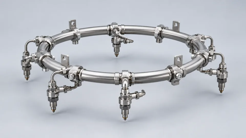
The test plan should specify whether the subject is a single nozzle, a combination of components, or corresponding channels. Different boundaries can affect the results, depending on the connectors and supply systems used. Defining clear boundaries helps avoid attributing all system performance to the component being tested.
Before starting the test, ensure that the connection direction, sensor status, and sampling settings are correct, and that the test conditions match those specified in the plan. For data that requires stabilization before recording, follow the appropriate procedures. The preparation process should also be documented, so that it can be reproduced and reviewed later.
Clamping, supply conditions, and data collection methods need to be consistent. Any abnormal phenomena should be recorded alongside the test data. Specific parameters are defined by the relevant product requirements.
Flow rates and other performance data should be presented together with the corresponding media and operating conditions. When using converted values, it’s necessary to explain the basis for the conversion and retain the original values. Listing just one number often isn’t sufficient to support product comparisons or manufacturing decisions.
When fluctuations occur, it’s important to distinguish between changes in supply, connection issues, and changes in the object being tested. Re-tests should have a clear purpose, and any differences from the original tests should be recorded. By systematically troubleshooting, it’s easier to establish a chain of causes, compared to repeated tests.
If there are any abnormalities in the flow data, it’s necessary to first check the supply conditions and connection status, followed by conducting targeted re-tests. If multiple components are replaced simultaneously, along with changes to the sampling methods, it becomes difficult to determine the cause even if the results return to normal. Keeping the troubleshooting steps clear and documenting each change helps convert test results into reliable manufacturing feedback.
Both original and re-test data provide evidence for problem analysis. Keeping these data along with their corresponding conditions helps explain how conclusions were reached, and it also facilitates comparison when similar phenomena occur in the future.
Result evaluation should consider both data and conditions. If re-tests are required, it’s important to explain the reasons and any changes compared to the original tests.