2026-09-29 4
The gearbox usually has multiple interconnected interface and positioning features. Manufacturing planning should also consider process accessibility, clamping stability and inspection methods.
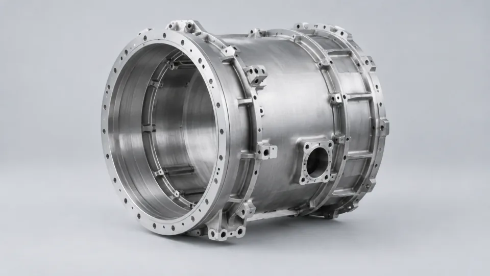
The various interfaces of the casing need to maintain their relative positions. Clamping planning should first identify these relationships, then consider positioning and support, rather than simply trying to fix the part at one time. The plan should explain the connection between the clamping state and the final inspection state.
Support must provide the necessary stability without interfering with processing and measurement. For areas with thin structures or poor rigidity, it’s necessary to evaluate the situation based on the actual shape. After changing the tooling, it’s necessary to check the features affected by the change, rather than continuing to use the previous conclusions.
The transfer of reference points between processes needs to be clearly recorded. For structures that are easily affected by support, key dimensions and shapes should be checked under appropriate conditions.
When the casing goes through different equipment or processes, the reference points, protective positions, and completed features need to be clearly transferred from one stage to the next. Transfer records should make it clear to the next stage which surfaces have been completed and which are still used for positioning, thereby reducing the risk of duplicate processing or misuse of reference points.
For deviations in multiple related features, it’s necessary to first observe the common directions and positional relationships, then verify the common reference points and corresponding processes. The support and procedure versions used during measurement should also be reviewed to avoid comparing data under different conditions directly.
It is assumed that the casing meets the requirements when clamped. However, changes in shape occur after removing the clamp. It is necessary to first check the evaluation criteria specified in the drawings, and then review the support and positioning schemes. The results of these two states should not be simply contradictory; rather, it’s important to understand what each state represents. Recording such differences during the process review can help improve the coordination between subsequent processing and inspection steps.
Clamping requires finding the right balance between positioning, stability, and the state of the part. The plan should be validated both structurally and technically, and adding constraints shouldn’t be seen as a universal solution to all problems.
After detecting deviations, it’s possible to review them in conjunction with processing records and inspection conditions, avoiding attributing measurement discrepancies to a single process.