2026-09-29 5
Thin-walled structures require attention to shape retention during forming, assembly and joining. When coordinating design and process, tooling space, joint accessibility and inspection conditions should be considered.
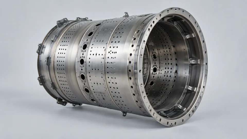
How components are disassembled can affect accessibility for forming, welding, and inspection processes. When comparing different plans, it is important to consider the number of components, the location of joints, and subsequent assembly steps. This helps to avoid situations where one part is easy to manufacture, but the overall connection or inspection becomes difficult.
Thin-walled components usually require proper support to remain in their proper positions during assembly. During the design phase, sufficient space should be allocated for tools and inspections, and it should be clear which features serve as positioning elements. The positioning methods should be adapted to the state of the components, avoiding the use of forced constraints that might mask underlying shape issues.
Discussion around the plan can focus on component placement, positioning features, and the order of connections. Areas that are sensitive to shape changes should have planned inspection and adjustment procedures in advance.
The order of connections can affect the constraints and accessibility of components. In the assembly plan, it is important to indicate stages where intermediate inspections are necessary, as well as areas that cannot be inspected after certain connections are made. Such flowcharts help ensure that designers, manufacturers, and quality control teams have a common understanding of the process.
Any difficulties encountered during assembly or inspections during the prototype phase can provide input for design improvements. Feedback should specify the exact locations, conditions, and impacts, rather than simply mentioning assembly challenges. Improvement proposals also need to take into account adjacent interfaces and functional requirements.
It is assumed that two thin-walled components, when connected together, may block the area where inspections need to be conducted. The design and manufacturing teams can jointly evaluate whether it is necessary to adjust the layout of the components, the order of connections, or the arrangement of inspections. When comparing different solutions, it is important to consider not only the ease of manufacturing but also the impact on functionality and interfaces. By incorporating inspection accessibility into the evaluation process early on, unnecessary disassembly or re-manufacturing during the prototype phase can be avoided due to insufficient evidence.
Changes in joint locations can affect both structure and function, and thus require appropriate design reviews. Manufacturing recommendations should specify the specific problems and conditions, and relevant personnel should work together to determine the most suitable solutions.
Prototyping records can help identify discrepancies between drawing requirements and manufacturing conditions, providing a basis for future design improvements.