2026-09-29 4
Heat exchange structures need to take into account heat transfer, flow resistance, interfaces and use space. When selecting a structure, you cannot just focus on a single heat exchange indicator.
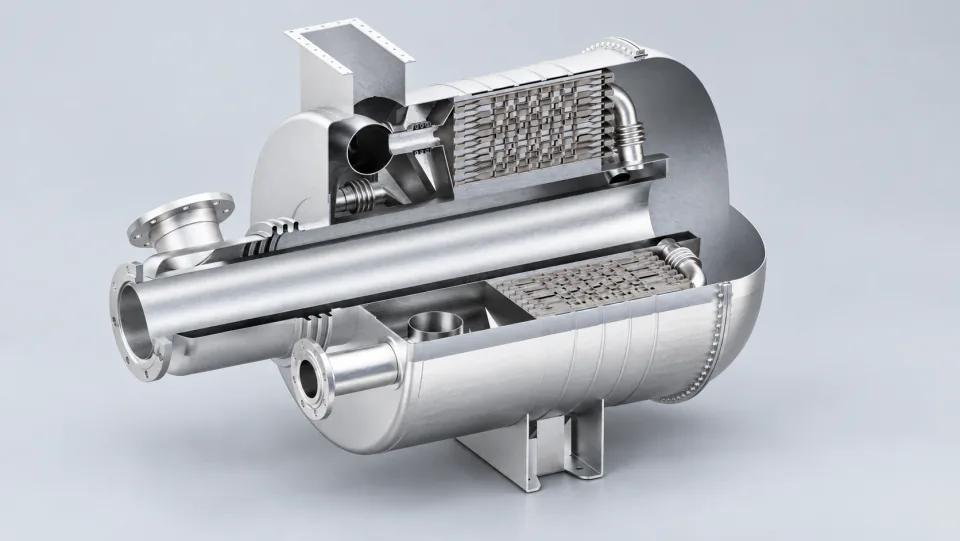
Different heat transfer solutions need to be compared under the same medium, flow rate, and temperature conditions. It is also important to clarify the allowed space, interfaces, and flow resistance requirements. Discussing heat transfer effects without considering the boundary conditions can lead to misinterpretation of data from different scenarios as if they were directly comparable.
When increasing the heat transfer area or altering the flow path structure, it is also necessary to assess the flow resistance and flow distribution. A slight improvement in one metric does not necessarily mean an increase in overall system benefits. The engineering solution should specify which metrics will be used for comprehensive comparison, rather than just presenting one optimal result.
Solution comparisons should be conducted under consistent boundary conditions, taking into account compatibility with other media, cleaning and maintenance requirements, and structural connection methods. The specific dimensions should be determined based on design calculations and verifications.
How the core component is connected to the shell, how the interfaces are arranged, and whether they can be inspected after use are all aspects that need to be considered in the design. In cases where there is a risk of contamination, cleaning and maintenance conditions should also be included in the discussion to prevent problems that arise after delivery.
The verification plan should correlate each design requirement with corresponding calculations, inspections, or tests. If any discrepancies are found, they should be rechecked against the model assumptions and boundary conditions. For areas where the performance has not yet been verified, clear records must be maintained to avoid making performance commitments without sufficient evidence.
It is assumed that a certain flow path solution increases the heat transfer area while also changing the flow resistance. When evaluating this solution, it is necessary to analyze both impacts under consistent conditions and to check the system’s allowable boundaries. Additionally, it is important to consider whether the interfaces, manufacturing processes, and maintenance requirements meet the desired standards. Only when the overall indicators align with the user needs can it be concluded that the solution is advantageous. It is not enough to simply present one aspect of the improvements.
Compactness is just one of the attributes of a solution. It is also necessary to evaluate the solution in terms of pressure drop, manufacturing processes, connections, cleaning requirements, and usage conditions. A balanced solution that suits specific tasks is more meaningful than one that focuses solely on reducing size.
The verification plan should correspond to the user requirements, covering all performance and integrity aspects that need attention, establishing a clear relationship between design inputs and test results.